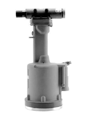
HYDRO-SHIFT CHERRYLOCK® RIVETER

Its durable, all metal housing makes this tool very robust for use in a shop environment.
This extremely powerful tool has been designed with many ergonomic features: low recoil, low noise and a comfortable fit in the operator’s hand. It can be operated in any posi-tion with one hand.
The H681 Series pulling heads fit directly on this tool to install both bulbed and standard NAS type 2000 Series CherryLOCK® Rivets. With the proper adapters and pulling heads, this tool can install other types of rivets. See the section on “Pulling Heads’’ for correct pulling head and adapter part numbers.
HOW TO USE THE G689:
Select the pulling head for the correct shank diameter and head style of CherryLOCK® rivet and attach it securely to the G689. For proper installation of the pulling head, see the pulling head tool sheet. Connect the air line to the tool.
Insert the rivet into the application. Place the pulling head over the rivet stem, pushing the tool until the pulling head is in contact with the rivet head. This will ensure full engagement between the jaws and the rivet stem. When pushing down on the rivet stem, make certain the tool is perpendicular to the application.
After activating the trigger, the tool will cycle, installing the rivet. After the stem breaks, point the tool toward an appropriate receptacle and release the trigger. The stem will eject from the front of the tool with a moderate force.
MAINTENANCE AND REPAIR:
The G689 has been manufactured to give maximum service with minimum care. In order that this may be accom-plished, the following recommendations should be followed:
1. The hydraulic system should be full of oil and free from air at all times.
2. Keep excessive moisture and dirt out of air supply to prevent wear of air valve, air cylinder and air piston.
3. Tool should be routinely inspected for oil leaks. Oil leaking around screws (39) indicates that a screw is loose or a Stat-O-Seal (38) needs replacing. Oil leaking around the small by-pass hole near the base of the handle grip (61) indicates worn or damaged O-Rings (64).

Отзывы ещё не добавлены